SVG vector drawings & STL 3D-printable models
SVG and STL are about communication, not fabrication. SVG goes in your presentation deck, your brochure, your website, or your laser cutter. STL becomes a tabletop reference model you can hand a client across a desk.
SVG — editable vector graphics
The SVG export is a ZIP archive containing one SVG file per sheet from the construction PDF — plan view, elevation(s), and every workshop sheet. Every line, polyline, and dimension label is a real vector element you can re-style, recolour, scale infinitely, or extract individually. There’s no rasterisation anywhere in the pipeline.
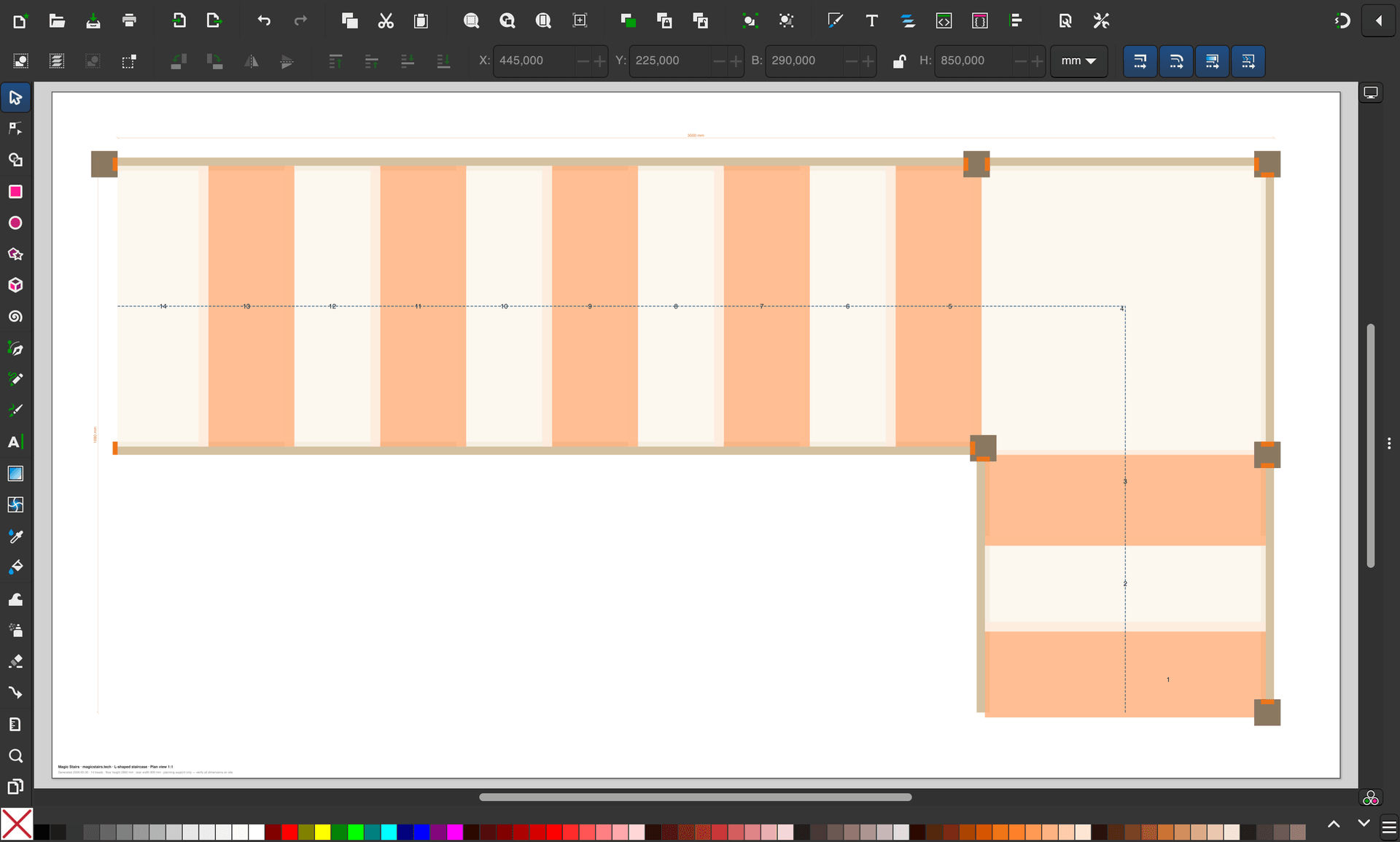
What’s inside the SVG file
Each SVG mirrors its PDF sheet 1:1, with these structural properties:
- Grouped by layer — every layer from the DXF (TREADS, STRINGER, BALUSTERS, HANDRAIL, DIM, …) becomes a named
<g>group in the SVG. In Inkscape and Illustrator, these show up as layers in the Layers panel. - Real units — the SVG
viewBoxis set in millimetres (or inches, depending on calculator unit) so anything you measure in the editor matches the physical staircase 1:1. - Selectable text — dimension labels are actual
<text>elements, not vectorised paths. You can change the font, size, or colour without losing the value. - Clean stroke widths — line weights match the PDF (heavy for outlines, light for dimensions). Scale the drawing and the strokes scale with it.
When to use SVG
- Client presentations — drop the elevation SVG into a Keynote, PowerPoint, or Figma slide. It stays crisp at any zoom level.
- Brochures & brand styling — open in Inkscape or Illustrator, recolour to match your brand palette, add logos, re-export as PDF.
- Website embeds — inline SVG in your marketing page so the staircase scales perfectly across retina and mobile screens.
- Laser cutting — both DXF and SVG export translate to a laser cutter; SVG is the friendlier path if your laser software (Lightburn, Glowforge, Beam Studio) prefers vector graphics.
Quick Inkscape workflow
- Download the SVG bundle from the calculator and unzip it.
- Open the sheet you want in Inkscape (free, open-source).
- Open the Layers panel (Object → Layers). Toggle off layers you don’t need (e.g. hide
DIMfor a clean reference image). - Select all (Ctrl-A) and apply a new stroke colour or fill if you’re restyling.
- Export as PNG (File → Export PNG Image) for a presentation, or save as SVG for further use downstream.
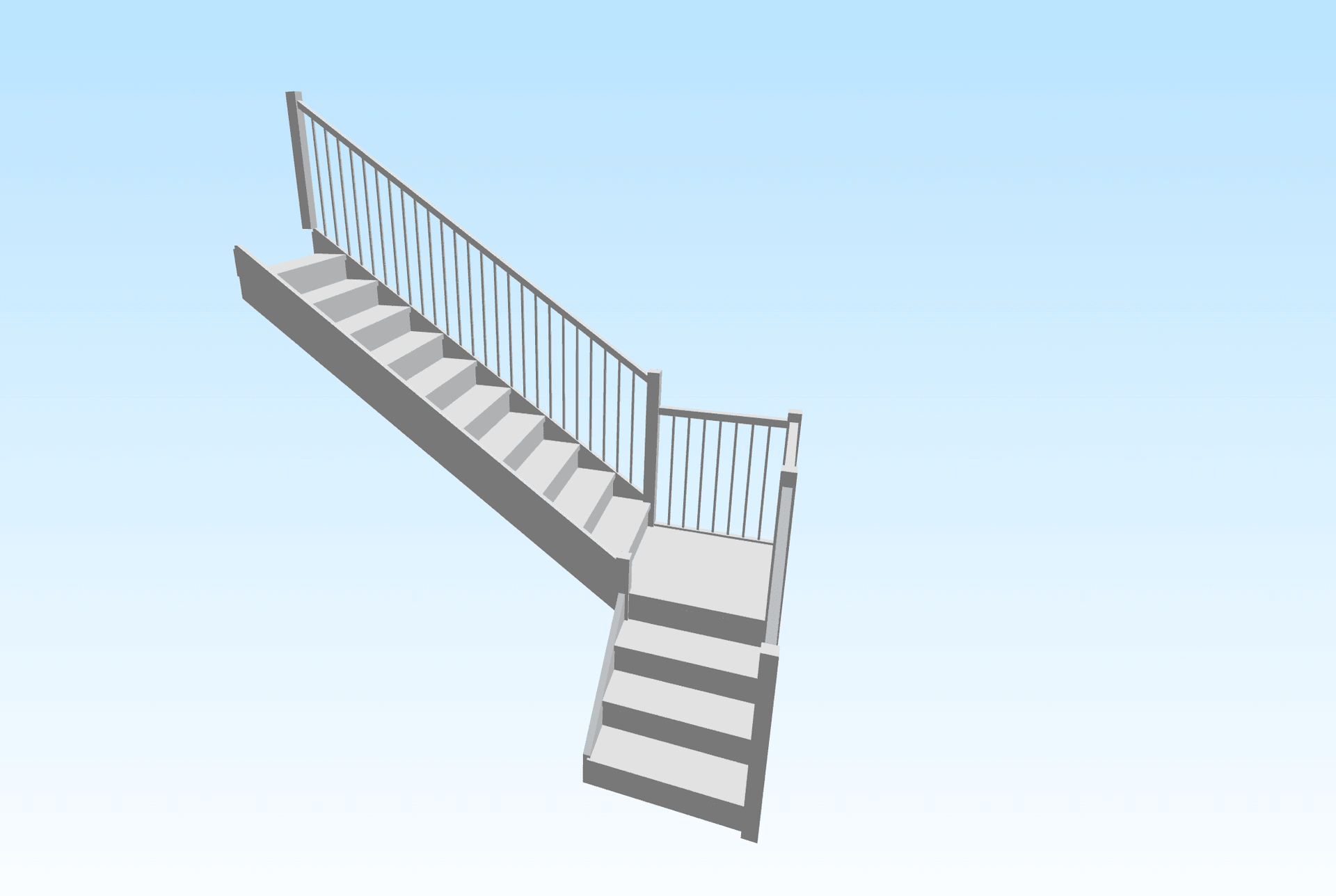
STL — 3D triangulated mesh
The STL export is a single binary STL file containing the entire staircase as one watertight triangulated mesh. It’s the format every 3D printer slicer reads natively. Use it when you want to hold a physical model of your design in your hand before a single piece of lumber is cut.
What’s inside the STL
- Single combined mesh — unlike STEP, the STL carries no part separation. Stringers, treads, risers, balusters, handrail, and newels are all welded into one continuous mesh.
- Watertight & manifold — generated from the same authoritative BREP geometry as the STEP, then triangulated. No naked edges, no internal faces, no holes a slicer would refuse.
- Real-world coordinates — the STL is at full size (millimetres) by default. You’ll scale it down in the slicer for printing.
3D-printing workflow
- Open the STL in your slicer (PrusaSlicer, Bambu Studio, Cura, OrcaSlicer — pick whichever your printer uses).
- The mesh imports at full size — typically 2–4 metres per side. Scale uniformly to ~5–10% to get a 200–400 mm desktop model. Most slicers have a single-input scale field for this.
- Orient the model so the staircase’s footprint sits on the print bed. The default orientation already has the foot at Y = 0, which is usually correct.
- Recommended print settings for a desk model: 0.2 mm layer height, 15% infill, supports OFF (the staircase geometry is self-supporting if printed footprint-down). A 1:30-scale L-shaped stair prints in roughly 4–6 hours on a typical FDM machine.
- Slice, save G-code, print. Sand lightly to take the stair-step artefacts off the treads if you want a hero model for a meeting.
What STL can NOT do
STL has well-known limitations — knowing them up front saves frustration:
- Not parametric. An STL is just a list of triangles. You cannot edit a dimension in CAD by opening an STL — for that you need the STEP export.
- No assembly hierarchy. Every part is welded into the same mesh. If you need to select a single tread in CAD or CAM, use STEP, not STL.
- Not for fabrication. STL is for visualisation and 3D printing. For actual CNC work, use DXF (2D) or STEP (3D).
Related exports
- PDF — eleven dimensioned A3 sheets ready for the workshop. See Construction PDF.
- DXF + STEP — 2D vector geometry for CNC and 3D solid geometry for CAD modelling. See CAD & CNC exports.