Construction PDF — page-by-page guide
Every Magic Stairs PDF export is an A3 landscape construction set ready for the workshop. Open it once and you’ll see eleven sheets — cover, plan, elevation, per-part workshop drawings, and a bill of materials. Here’s what’s on each.
The construction PDF is the format most users need first. It’s self-contained (no software required to open it), reads cleanly on screen and on paper, and carries every dimension a carpenter or CNC operator needs to cut the parts. The sheets are ordered the way you’d build the stair: read the cover, check the plan, mark out the stringers, cut the treads, drill the newels, order the materials.
Sheet 1 — Cover & project summary
The cover sheet is your quick-reference project card. The 3D preview on the left shows the staircase you designed, locked to a fixed isometric angle so the proportions read the same in every export. The right column carries the Key Parameters table (floor height, step count, tread depth, rise per step, slope, stride, footprint, stringers, railing), the live Geometry Check panel, and the totals — stringer length, handrail length, baluster count, tread area.
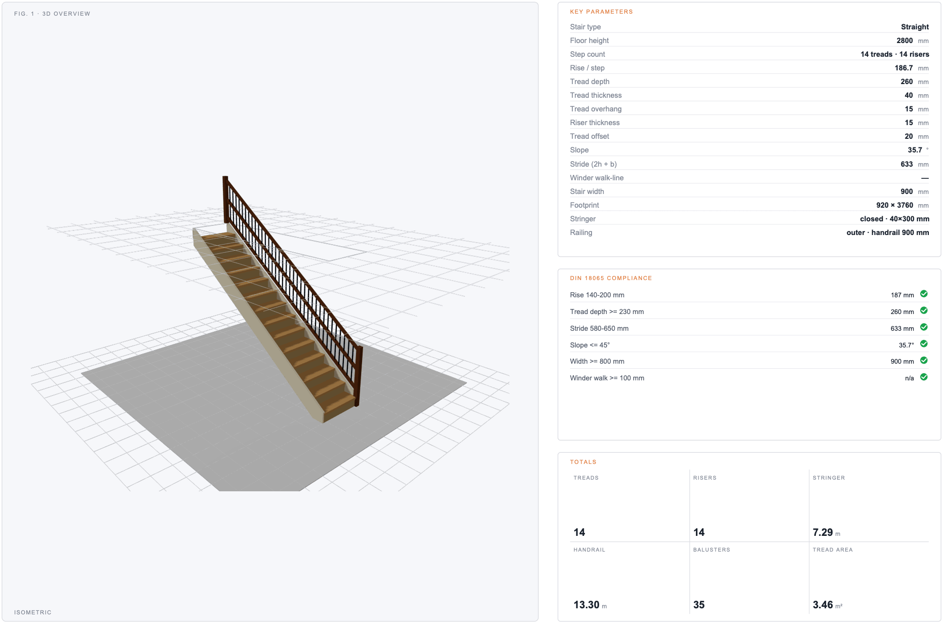
If a parameter on the cover doesn’t match what you expect, change it in the calculator and re-export — the PDF and the live preview are generated from the same authoritative geometry, so they never drift.
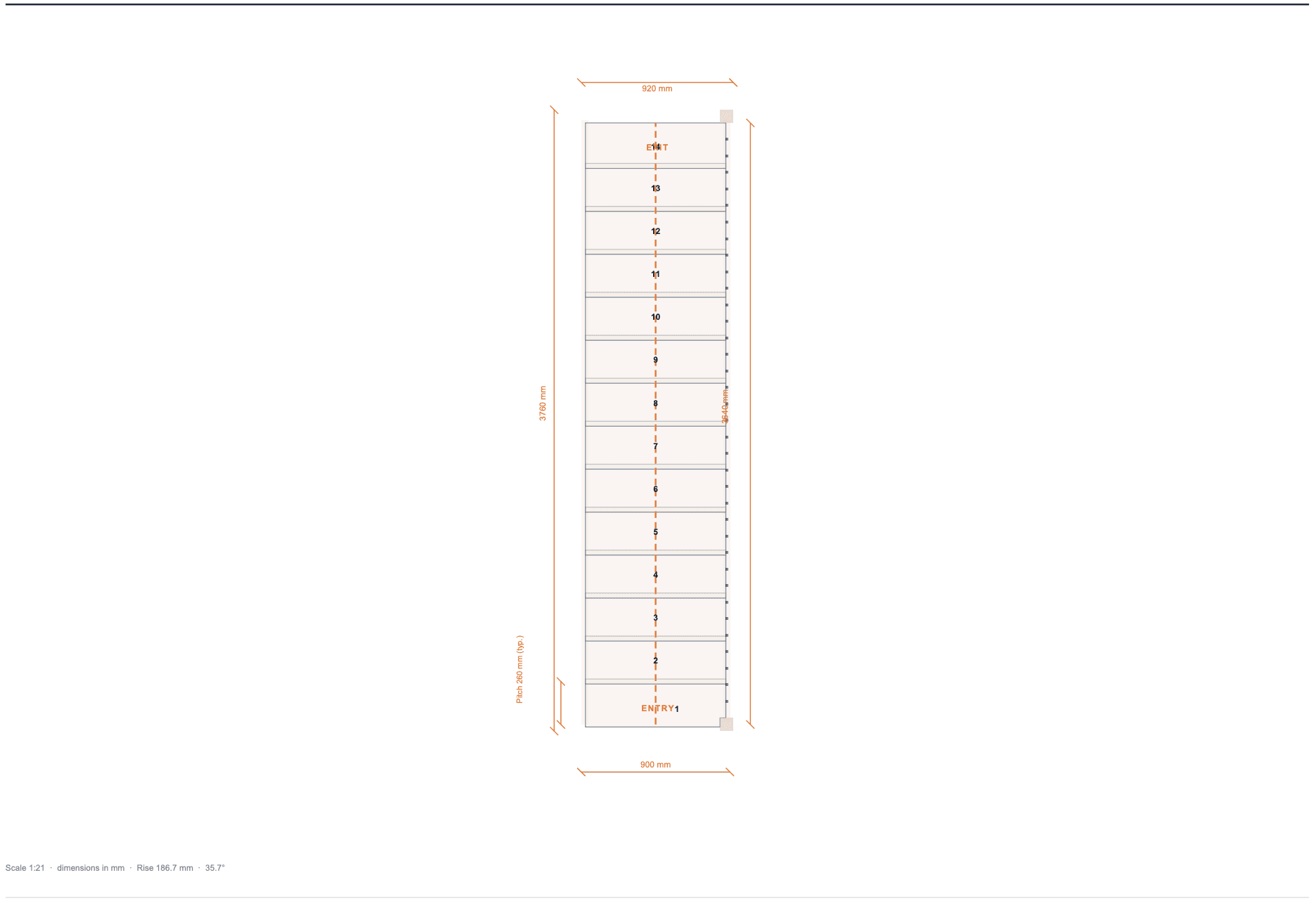
Sheet 2 — Plan view (top)
The plan view shows the staircase from directly above, drawn to the scale noted in the lower-left meta strip (typically 1:7 or 1:11 depending on stair size). Every step is numbered, the walking line runs through the centre as a dashed orange polyline, and the outermost dimensions on the page span the total footprint — width and depth — that the stair occupies on site. Per-step Pitch dimensions on the left tell the carpenter what spacing to mark out.
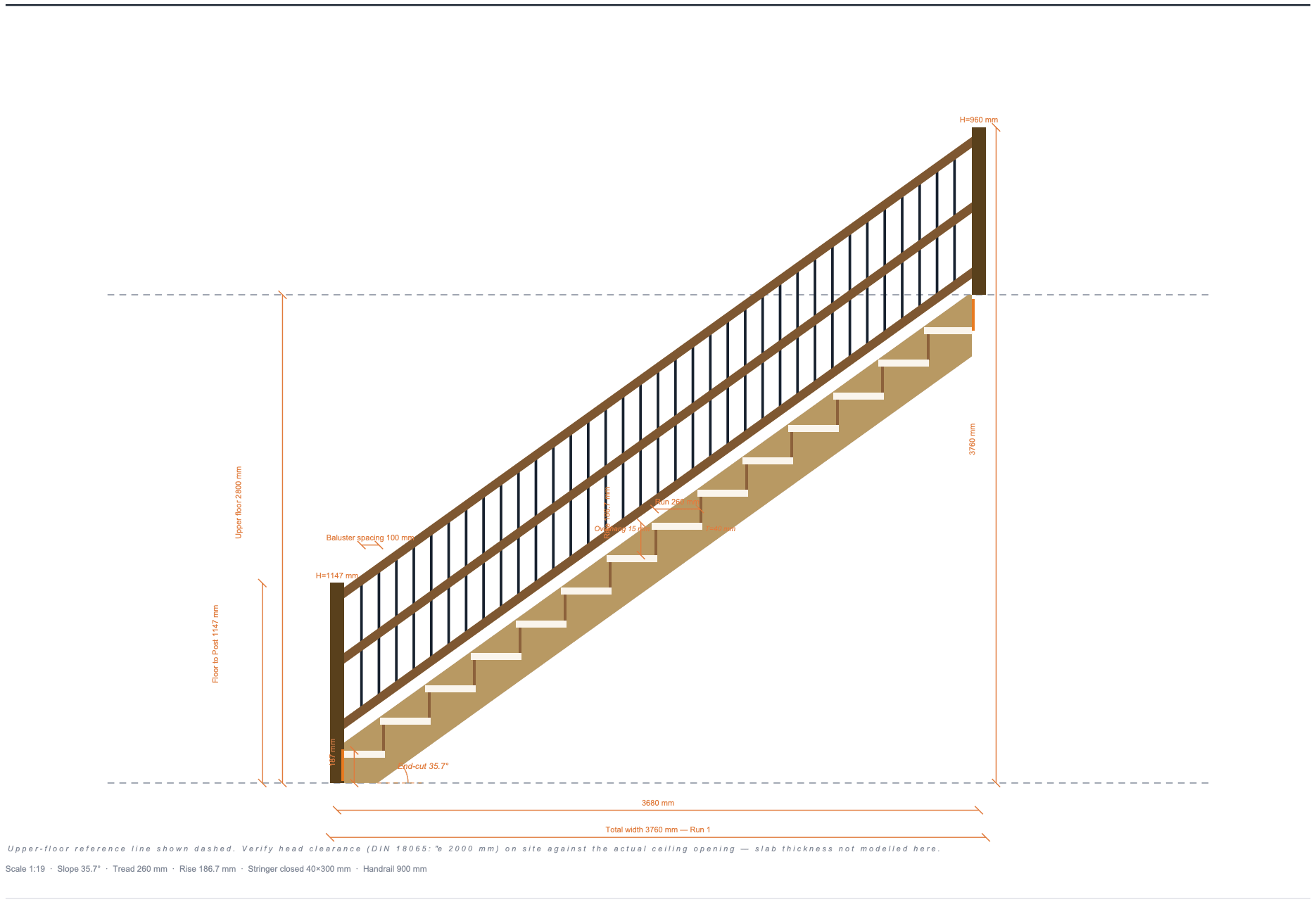
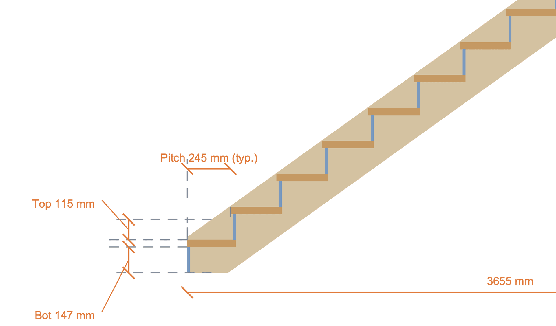
Sheet 3-4 — Elevation (Run 1, Run 2)
Elevation sheets render the stair from the side — the view a person standing next to it would see. For L-shaped stairs there are two elevation sheets, one per run. For straight, porch, and ladder stairs there’s a single elevation sheet.
Inside the drawing area you’ll find the stringer profile, the treads, the risers (when enabled), every baluster, every rail (upper handrail plus optional lower rail and intermediate rails), and an angle arc at the slope-meets-ground corner labelled End-cut 37.6° — the angle the carpenter cuts at the foot of the stringer board. Dashed reference lines mark the lower and upper floor levels.
Sheet 5 — Stringer · Workshop
The stringer workshop sheet is the single most important page for anyone cutting the slabs. Each unique stringer (inner, outer, mid-N for porches with three or more stringers) gets its own panel showing the full saw-tooth or closed-stringer profile at 1:9 or 1:10 scale.
Around the profile you’ll find a complete dimension chain: Run + Rise of one typical step (the rest are identical and omitted to keep the drawing readable), the bbox width and height, AND — and this matters for CNC — the length of every unique edge: the foot bottom, the slope diagonal, the back vertical, and the foot vertical. Closed stringers additionally show the dado-pocket position chain so the carpenter can mark out where each tread sits in the slab.
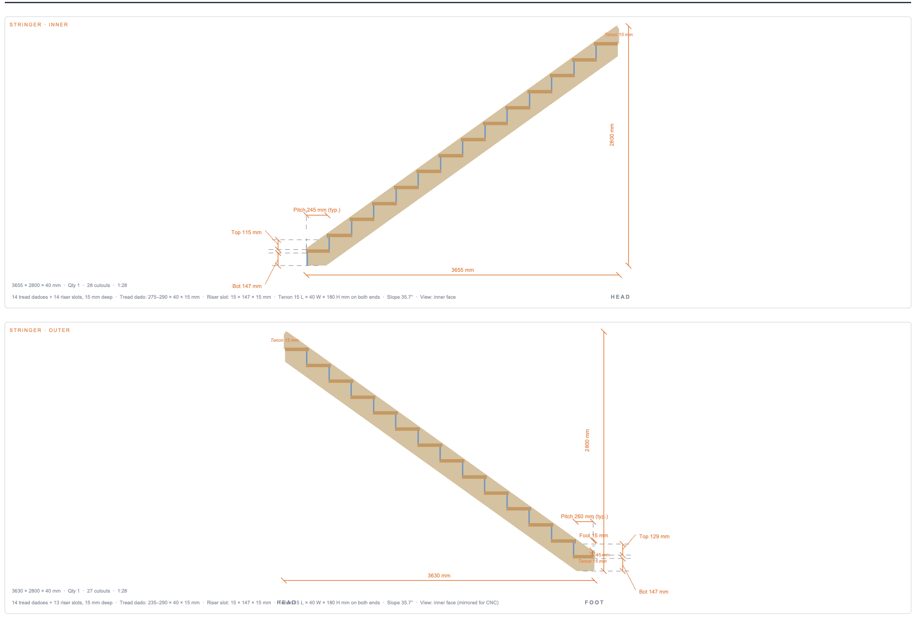
For non-rectangular stringers (winders, corner pieces) the dimension chain also includes every non-90° interior angle, so the carpenter can lay out the polygon from the drawing alone without re-running the geometry.
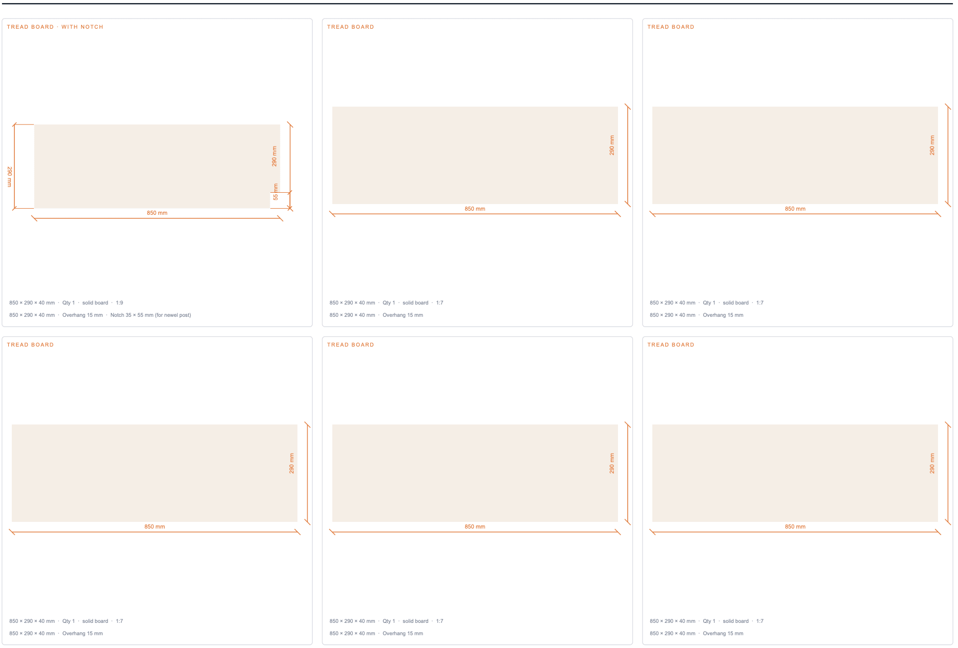
Sheet 6 — Treads · Workshop
Treads are grouped by shape: identical boards collapse into one card with a quantity badge so the workshop can batch-cut them. A typical straight staircase emits two tread cards — one for the first tread (which has a corner notch for the foot newel post) and one for all the rest. Notched treads carry a per-edge dimension for every cut, including the short edges of the notch itself.
Sheet 7 — Risers · Workshop
Riser cards appear only when the calculator haswithRisers = true. Each riser board is shown at 1:1 outline, dimensioned, with a quantity badge for batching. Outdoor porch stairs typically ship without risers — you’ll notice this sheet disappears from the page count automatically.
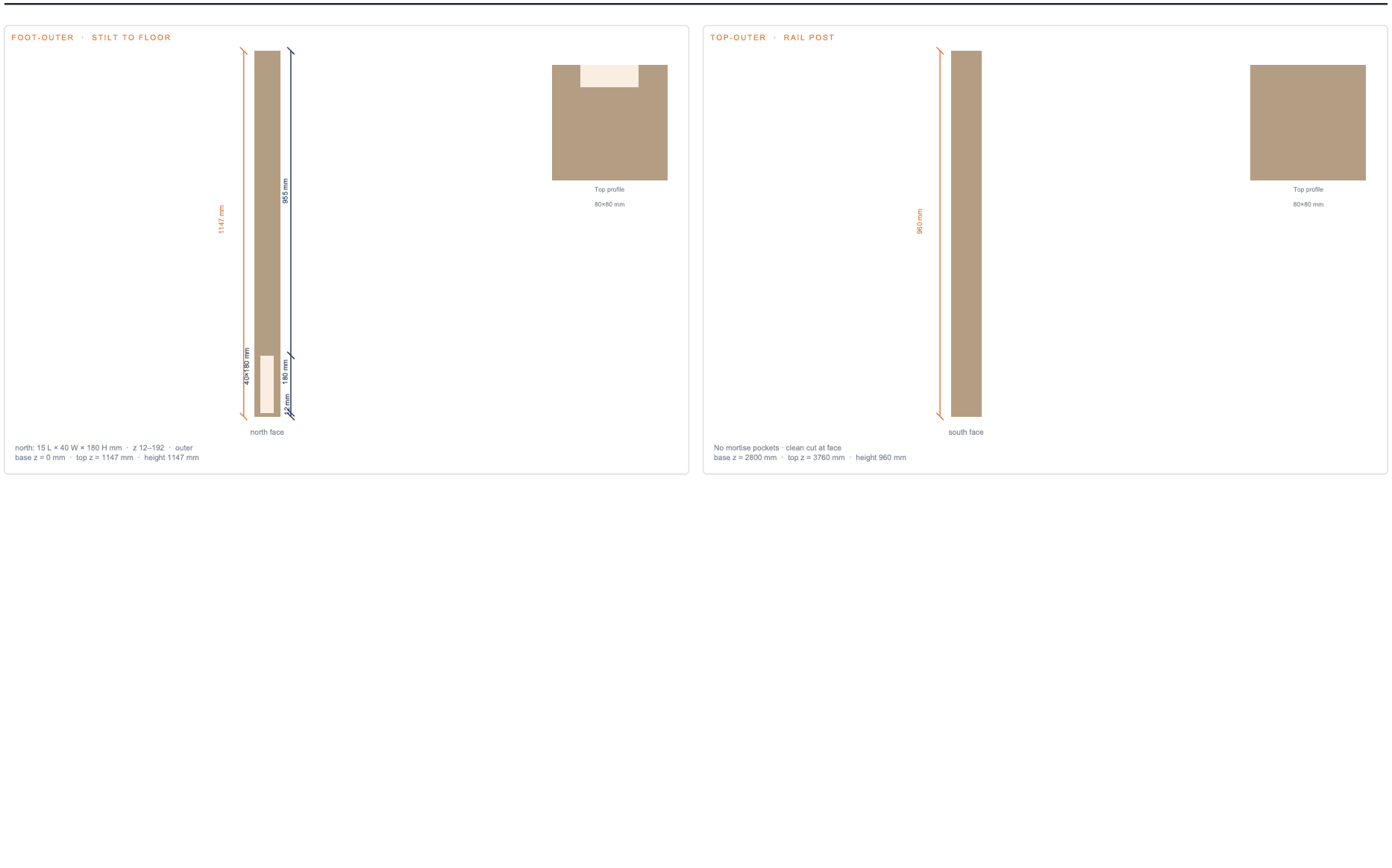
Sheet 8 — Newel posts · Mortise details
Newel posts are tricky because the joinery lives on multiple faces. This sheet renders each post as a single 4-face “unfolded” elevation — north, south, east, west — laid out side by side, with every mortise pocket coloured in. The pocket rectangles are dimensioned in post-local coordinates so the carpenter can clamp the post in a vice and chisel out the cavities directly from the drawing.
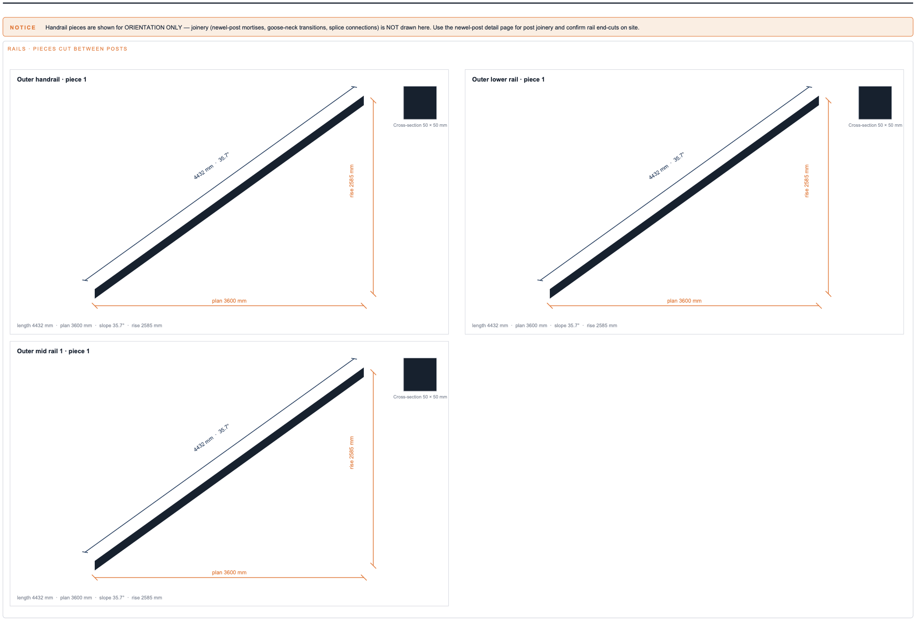
Sheet 9 — Handrail · Workshop (every rail piece)
The handrail workshop sheet shows ONE card per cut piece, across every rail — upper handrail, lower (knee) rail, and any intermediate rails. Each card carries a small isometric preview plus three dimensions: plan length (the horizontal distance the rail covers), rise (the vertical rise across that piece), and length (the actual diagonal cut length — what the carpenter measures on the board) together with the slope angle.
When the railing system has lower or intermediate rails (set in the calculator via the Lower Rail Height and Rail Count controls) the workshop sheet automatically adapts the grid — 2-up for ≤ 6 pieces, 3-up for 7–12, 4-up for more — so every card stays readable regardless of how many rail pieces the configuration produces.
Sheet 10 — Balusters · Workshop
Balusters are grouped by physical signature (bbox dimensions rounded to 1 mm) — identical balusters share a card with a quantity badge. The card shows the side-view outline, which depends on whether the baluster sits on the sloped lower rail (parallelogram, both top and bottom angled to match the slope) or directly on a flat tread top (trapezoid, square-cut bottom). The card’s notes line includes the top angle, the bottom cut (angled or square cut) and the cross-section.
Sheet 11 — Bill of Materials & Notes
The final sheet is the BOM. Every part is listed with quantity, L × W × T dimensions in the active unit, material suggestion, and a short notes column (e.g. Front overhang 20 mmon the first tread, Saw-tooth profile on each stringer slab). The totals row sums stringer length, handrail length, baluster count, and tread area so you can phone the lumber yard with a single number per category.
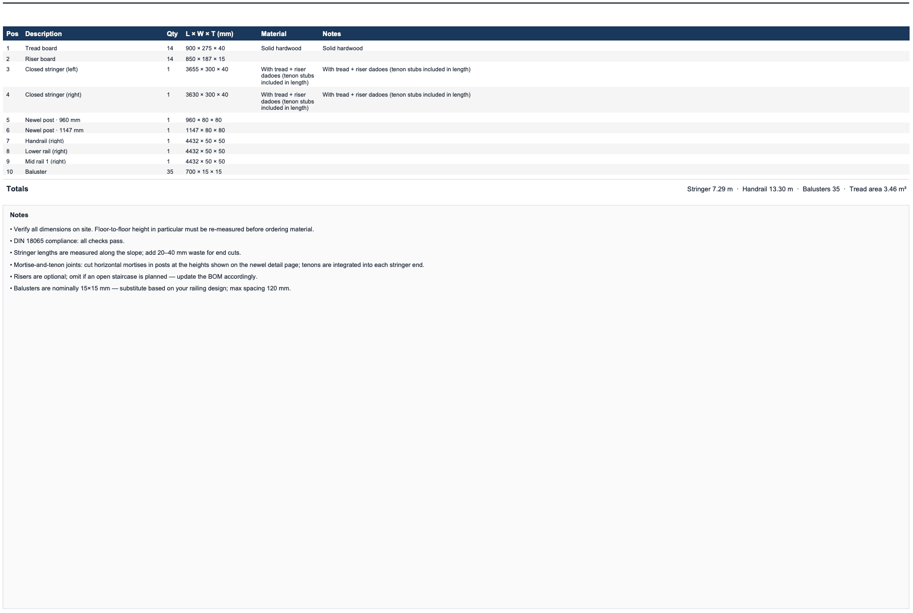
Below the table is a free-text notes block with general carpenter reminders: re-measure on site before cutting, add waste for end cuts, use a wood species rated for the use case, treat end-grain on outdoor stairs, and so on. Notes are calculator-specific — porch stairs include outdoor-treatment notes that don’t appear on indoor staircases.
For planning only — verify on site
Every Magic Stairs construction PDF carries a footer warning on every page: FOR PLANNING ONLY — VERIFY ON-SITE DIMENSIONS. This isn’t boilerplate cover-our-back text — it’s a real instruction. The PDF is generated from the parameters you entered into the calculator. If the floor-to-floor height you measured was off by even 10 mm, every step rise computed by the calculator is also off, and the staircase will arrive at the upper floor at the wrong elevation.
Before you cut anything, re-measure the actual floor-to-floor height at the build site, re-enter it into the calculator, and re-export the PDF. The export takes about a second; cutting the wrong stringer takes about a day.
Local building codes (DIN 18065 in Germany, IRC R311 in the US, BS 5395 in the UK) may impose limits the calculator’s geometry check doesn’t enforce — particularly around handrail height, baluster spacing, and headroom clearance. If you’re building inside a permitted dwelling, have a local professional sign off on the design before fabrication.
Related exports
The construction PDF is the most accessible format, but it’s not always the right one for the next step in your workflow:
- DXF + STEP for CNC routing, CAM toolpaths, and 3D CAD modelling — see CAD & CNC exports.
- SVG for vector-perfect client presentations, and STL for a tabletop 3D-printed reference model — see SVG & STL exports.